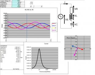
This simulation shows:
- the voltages as they would appear on an oscilloscope screen
- the (static) phasor diagram as you would (or perhaps should!) draw it
- A graph of current against frequency, showing how the amplitude of the current would vary with frequency. In the case of the RL and RC circuits, they behave as ??-pass circuits, while the LC and RLC circuits show a distinct resonance.
You can set any of R, L, or C to zero to get a simpler (eg RC) circuit and slide the time around to watch the phasor rotate (slider under the sine waves).

Electromagnetics ... a "Toy-box" by Alan Murray, University of Edinburgh is licensed under a Creative Commons Attribution-NonCommercial-ShareAlike 4.0 International License.


